SLS and Orion - Our ride back to the Moon
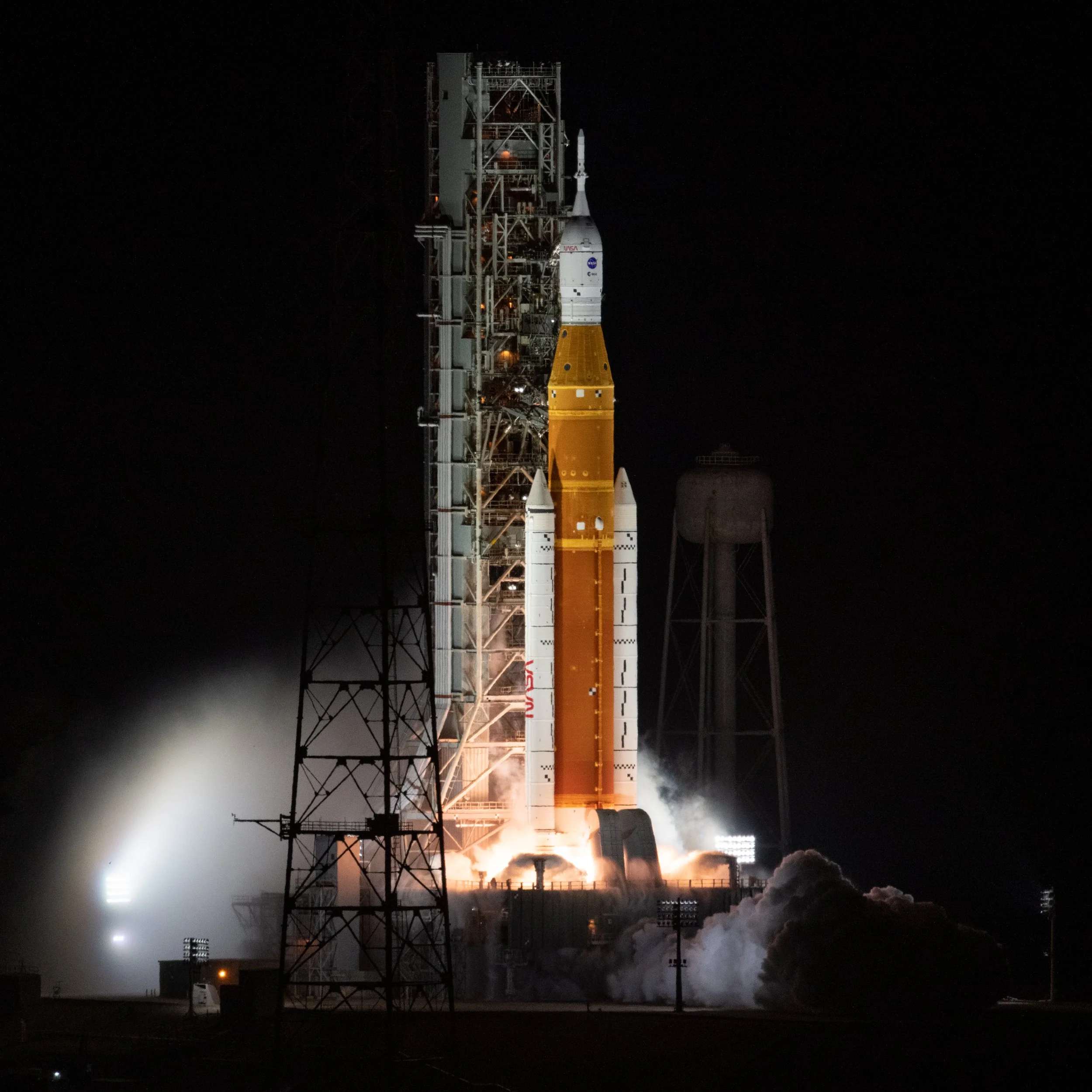
Artemis I Ignition
Credit: NASA
SLS and Orion, a duo that tears the spaceflight community in two. Some argue it's past its time, too expensive, and too slow, while others argue it's necessary and our only present option for returning man to the Moon. Built upon the shoulders of the Shuttle program, harnessing past hardware and modernising them to fit the bill of Lunar exploration, the Artemis program promises to bring us back to the Lunar surface, this time to stay.
Artemis II, the second launch of the Artemis programme, is gearing up for a manned Lunar flyby, NET February 6th. The SLS and Orion stack is out at LC-39B at Kennedy Space Center, awaiting a WDR test (Being conducted as of writing). This test is the final checklist item before a launch can go ahead. Read more about the rollout and the steps towards launch and WDR here: https://www.theweeklyspaceman.com/articles/artemis-ii-rollout-one-giant-leap-towards-launch Once WDR is complete, MMT will come together to figure out the best launch date for the Artemis II launch. Once a launch date has been set, SLS will ignite its 4 engines and 2 SRBs to produce a total of 8.8 lbf at liftoff, firing our 4 astronauts to LEO (Low Earth Orbit). More on this a little later on as we dive into the workings of SLS and Orion to give you an idea of how these beautiful machines work and how they come to be ahead of launch.
What is Artemis?
Before we get into SLS and Orion, we need to understand what they are used for. Artemis is a lunar programme run by NASA. Artemis promises to extend and better the goals of the past Apollo programme, aiming to make a permanent human presence on the Moon. Although it has not been a smooth journey thus far. From delays and setbacks to cancellations and budget cuts, Artemis has been through it. Although things are so positive right now as we approach Artemis II, the spaceflight community has generally been negative and confused by the path NASA has chosen. Harnessing past hardware and revolutionising it for current needs – you’d think this would make things cheaper. You were wrong. At an incredible development cost of $90b, the Artemis program absolutely has not shown for it in terms of vehicle and flight output.
SLS (Space Launch System)
SLS is a super heavy-lift class launch vehicle, being the only current vehicle able to propel a manned capsule (in this case, Orion) around the Moon. Developed by NASA with aid from commercial customers such as Aerojet Rocketdyne, Boeing, Northrop Grumman, and ULA (United Launch Alliance). SLS stands at an incredible 98m tall, boasting its orange beauty across the Cape; it's a true testament to American engineering. Development of SLS started in 2011 following the cancellation of the Constellation program, to take over the Ares family. As mentioned before, SLS uses past Shuttle hardware, such as the RS-25 engines and SRBs. The use of off-the-shelf hardware was an attempt to cut costs of development; however, this was not the case. With development costs already reaching the $24b mark, spaceflight fans would have hoped for more by now. What could cause higher costs if they’re just using past hardware? Well, first of all, there are not enough leftover parts to support more than 8 missions and only 16 RS-25s, which can support 4 missions. Due to this, new production lines to build new expendable RS-25 variant (RS-25E) are required; these are expected to cut engine costs by 30%. Development of a new SRB is also needed; this is where the BOLE (Booster Obsolescence and Life Extension) programme comes in. Using casings derived from the cancelled OmegA launch vehicle, an upgraded design came to life in the form of Demonstration Motor-1. A test article aimed to push the limits of the booster design. A first test fire of this motor took place in June 2025, where DM-1 suffered a nozzle anomaly roughly 2 minutes into the firing; however, the test exceeded expectations, producing 4 million lbf and exceeding other metrics too!
What’s on the pad?
Now let's get into the configuration/version of SLS that is sitting out on LC-39B as we speak. Starting at the bottom, we got the engine section, consisting of many features such as the 4 RS-25 engines, propellant ducts, the thrust structure, avionics, and the bottom attachment point for the SRBs. This section is a single barrel standing 6.86m tall. Made of aluminium isogrid panels to reach the high strength-to-weight ratio needed to take the thrust forces of the 4 RS-25 engines.
Moving on up, we have the tall liquid hydrogen fuel tank, made up of 5, 6.7m tall barrel sections welded together to form one large tank. At either end of the tank are dome caps to enclose the tank, for … well, obvious reasons. This tank holds 537,000 gallons of liquid hydrogen. Liquid hydrogen serves as the fuel for the RS-25 engines and is incredibly efficient, allowing the first stage to burn for 8 minutes!
Once again moving upwards, we got the intertank segment. An empty 6.64m tall barrel section that encloses the top dome of the liquid hydrogen tank and bottom dome of the liquid oxygen tank. The intertank also serves as the forward connection for the 2 SRBs and contains a thrust structure to carry the forces enacted by the SRBs. On top of that, it also houses 2 cameras and more avionics components. Unlike the liquid hydrogen tank sections, the intertank is bolted to the two tanks using 7500 bolts. The use of bolts provides the high strength needed to carry the incredible forces of the engines and weight of the liquid oxygen tank.
While on topic, let's move on to the liquid oxygen tank. This large tank, consisting of 2 4.75m barrel sections and 2 domes, has a total capacity of 196,000 gallons of liquid oxygen! Similarly to the liquid hydrogen tank, the structure is made of aluminium isogrid panels. Now, you may be wondering how the liquid oxygen actually gets to the engines, considering it has an intertank (or interstage) and a ginormous liquid hydrogen tank in its path. Well, that’s what those 2 lines on the external wall of the core stage are for; those lines deliver the liquid oxygen to the engines, saving complex piping through cryogenic propellants.
The final part of the core stage assembly is the forward skirt. The forward skirt is 3.17m tall and houses most of the avionics systems. Another responsibility of the forward skirt is tower connections. This is where the tower umbilicals and the vehicle stabilisation system latches on to the rocket. It also has an aluminium isogrid panel structure, like the other high load areas of the core stage. This is needed, as the forward skirt is the part where the spacecraft and ICPS stage connect to the rocket via adapters.
We are flowing beautifully here; once again staying on topic, let's talk about the ICPS/Orion stage adapters. Known as the LVSA (Launch Vehicle Stage Adapter), this cone shaped structure stands 8.38m tall and connects the ICPS stage to the SLS rocket. The cone structure has a bottom diameter of 8.41m, connecting to the 5.09m diameter ICPS stage at the top. This adapter doesn’t just serve as a structural interface between the rocket and ICPS stage; it also protects the ICPS avionics and other delicate systems from the violent vibrations seen during launch. Once the core stage depletes its propellant, a pyrotechnic separation system kicks in, allowing the ICPS stage to separate itself from the core stage.
The next and final adapter is also the final part of the SLS assembly. The OSA (Orion Stage Adapter) is 5.5m in diameter and 1.5m tall and is made of a lightweight aluminium. This obviously connects Orion to the stack but also serves a second purpose… housing CubeSat payloads! That’s right, Artemis II will carry some scientific CubeSats.
The final piece of the puzzle is the Orion spacecraft. We will get into this a little later on.
ICPS
Built by ULA (United Launch Alliance) in collaboration with Boeing, the ICPS (Interim Cryogenic Propulsion Stage) is a modified Delta family second stage, optimised and upgraded for Artemis. As the name suggests, this stage uses cryogenic propellants, the same cryogenics as the core stage. The stage is 5.09m in diameter and 13.7m tall. Many of the modifications include increased propellant capacity, such as a stretched liquid hydrogen tank and an additional hydrazine can for increased RCS usage.
The stage is powered by the RL10 engine, an engine used for over half a decade. The engine has a mass thrust output of 24,800 lbf and a specific impulse (ISP) of 462 seconds. Like the core stage, the ICPS uses hydrolox as its propellant, simplifying tower and ground-side systems. This stage will perform a few burns on Artemis II. Once SLS’ core stage completes its burn, Orion will be placed in an initial 115 by 1800 mile orbit. The first ICPS burn will raise the perigee of Orion from 115 to about 235 miles. The second burn will raise the apogee to about 68,000 miles above Earth, putting Orion into a 235 by 68,000-mile orbit. This orbit will take roughly 42 hours to complete. After this burn, Orion/ICPS separation will occur. However, the ICPS is not done yet. It will be used as a target for Orion's proximity operations demo that will occur at T+3h24m15s into flight.
Orion
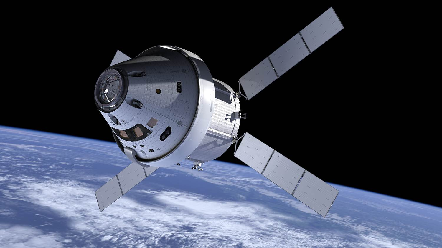
Animation of Orion and the ESM on orbit
The Orion spacecraft is the capsule used in the Artemis programme. Its objective is simple: take a crew of 4 to the moon and safely return them to Earth, an objective demonstrated on Artemis I. Although it didn’t come without its troubles. During re-entry, Orion’s heat shield didn’t work as planned, and even though the capsule returned safely, it was far from ideal for NASA after such a successful mission. Like many other aspects of the Artemis programme, Orion uses past-era, such as Apollo and Shuttle era derived technology.
Let's jump into the capsule and learn more about how the system works. The Orion capsule is made up of 3 major components: the Launch Abort System (LAS), the Crew Module (CM) and the Service Module (SM). This time, let's start from the top and work our way down.
The LAS is the tall (15.25m) white pole-like structure sat on top of the rocket. As the name goes, the main objective of the LAS is to safely pull Orion away from SLS if the need arises. To do this, a powerful motor is needed, and a powerful motor is what they got. A 400,000 lbf motor firing through 4 nozzles powers Orion safely away from SLS in seconds. This motor is known as the abort motor. Joining the abort motor are the jettison motor and attitude control motor. The jettison motor is designed to pull away from Orion once it either reaches the LAS jettison point in flight or completes the abort motor burn following a launch abort. Once ignited, the motor will produce 40,000lbf. This allows Orion to safely deploy its parachutes, ready for splashdown, with the LAS a safe distance away. And finally, we have the attitude control motors. 8 equally spaced out valves ready to push/steer Orion in any direction it needs This motor produces a total of 7,000 lbf.
Below the LAS is the CM. The CM will house the crew of 4 during their 10 day mission around the moon. The Orion CM has a very similar appearance and function to the Apollo CM. With a base of 5.02m and height (or length) of 3.3m,Orion's CM boasts an impressive 50% increase in habitable volume over Apollo’s CM, taking the total volume to 8.95m³. As expected with technology advancing and whatnot, Orion does carry some upgrades over the previous moon capable capsule. Orion CM has many features, such as digital control systems instead of the hundred switches and buttons; it also has autodock features like all the other modern spacecraft. However, if needed, the crew can and will be able to take manual control, with this being demonstrated during the Orion/ICPS close proximity ops demonstration.
Now let's look at the similarities between Orion and other NASA crewed vehicles such as Apollo and Shuttle. The structure of Orion is constructed using an advanced lightweight aluminium-lithium alloy that features a honeycomb structure. The honeycomb structure increases strength in the walls of Orion. Shuttle and Apollo both use aluminium alloys in their primary structures. The heat shield is made up of materials used by Apollo. Using an ablative heatshield method made of Avcoat ablator. Avcoat is made of silica fibres with epoxy resin in a fibreglass honeycomb. This heat shield worked well on the Apollo programme but did encounter an issue during Artemis I. Following testing and studies, NASA concluded that the Avcoat was not permeable enough, meaning gases would build up in the heat shield, causing pressure to build up and inevitably ripping off chunks of the heat shield material, as well as forming cracks on the exterior of the heat heatshiled. To counter this, NASA has changed the re-entry trajectory to reduce heat exposure and keep it within limits. To pull off this trajectory (and any re-entry trajectory), the spacecraft needs to come in at the correct angle. In order for Orion to do that, it has been equipped with 12 Reaction Control System (RCS) thrusters, each producing 160 lbf. Another thing the three big spacecraft have in common is their parachutes. Although they aren't the exact same, they are made up of similar materials. The main material used in all 3 is nylon. The parachute system on Orion has a total of 11 parachutes: 3 forward bay cover parachutes, 3 drogue parachutes, 3 pilot parachutes and 3 main parachutes.
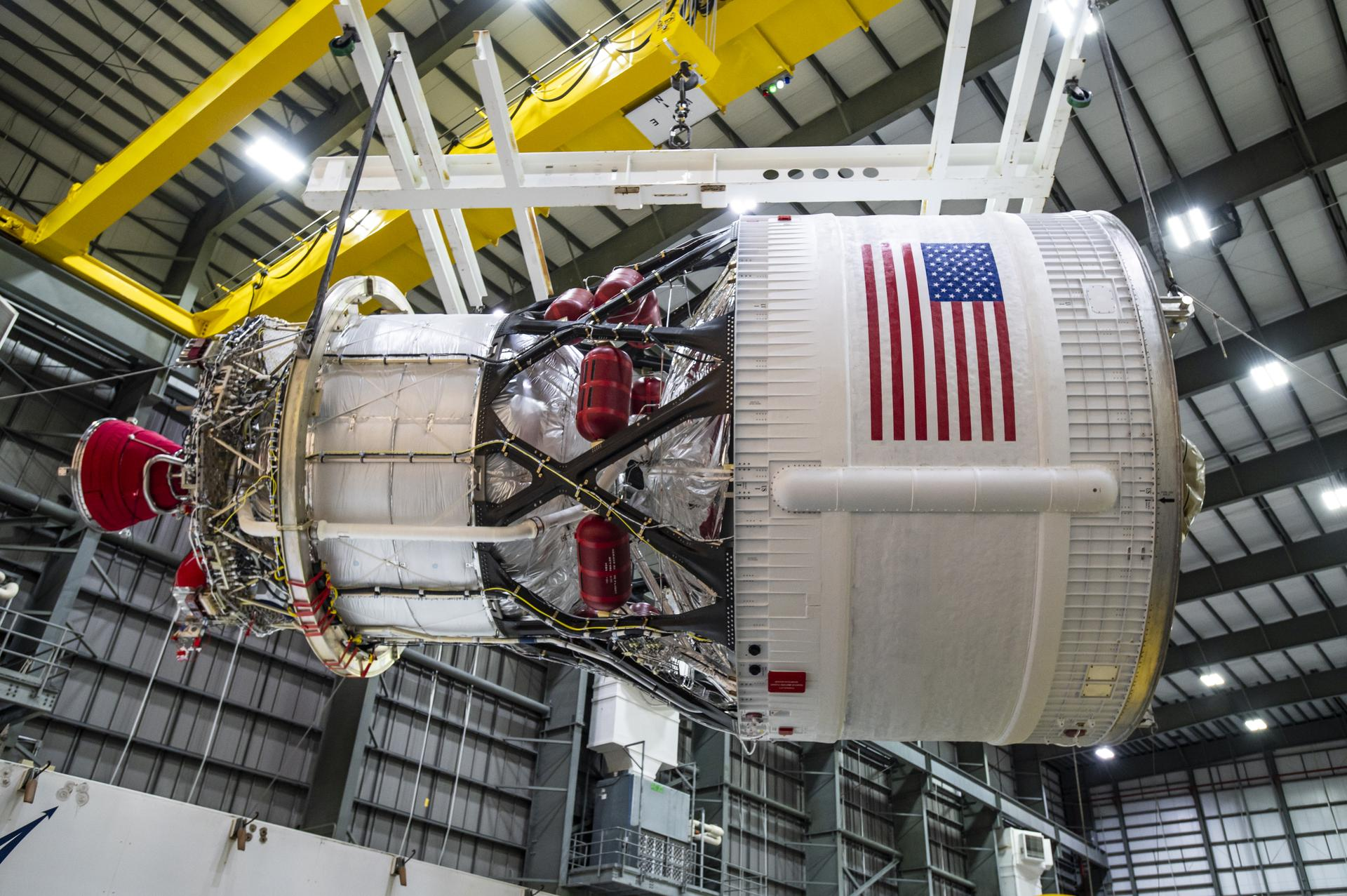
Now let's take a look at the European Service Module (ESM), which is Orion's SM. The ESM's main job is to provide propulsion, power and life support for the crew. It allows the spacecraft to manoeuvre in space, which is important for docking and the close proximity ops demo. The ESM is 4m in height (or length) with a 4.1m diameter and a 15.4t fully fuelled mass. This is smaller than the Apollo SM but has more performance in everything besides propulsion. The ESM solar panels are ~7.3m long and generate 11.2kW of power compared to Apollo's 6.2kW, although Apollo used fuel cells instead of solar panels. The ESM is powered by 1 main engine, 8 auxiliary thrusters and 24 RCS thrusters. The main engine used is the Aerojet AJ10 engine, which provides 6,000 lbf. The 8 auxiliary thrusters are Aerojet R-4D engines providing 110 lbf each. Finally, there are 24 RCS thrusters provided by Airbus, providing 49 lbf each. The propellant used is MON-3 (Mixed Oxides of Nitrogen) and MMH (Monomethylhydrazine), and these are stored in 4 tanks made of titanium. The ESM is responsible for all manoeuvres, including the close proximity operations demonstration, the TLI burn and the Return Trajectory Correction (RTC) burn. The ESM will then separate from Orion following the RTC burn and then burn up in Earth's atmosphere during re-entry.
Summary and personal views
As of writing, SLS is currently in the final phases of its Wet Dress Rehearsal. If all goes well, we will hopefully get a launch attempt towards the end of the February window! Hopefully you learnt a bit more about SLS and Orion in this and can explain some systems to your family and friends who may not know what’s happening.
This mission is the most historic mission in a long old time. This may not be a Moon landing or even a Lunar orbit, but this will be the farthest a human has ever gone into space. Please gather your friends and family and witness history, together. We are the Artemis generation, and we are going to stay!
Follow us to stay up to date on all things Artemis II, especially in the lead up to launch.
If you want to learn more about the mission profile, read my good friend Magnums article here: https://www.theweeklyspaceman.com/articles/artemis-ii-mission-profile
I welcome any constructive criticism so if you have any improvements you think I could make, please let me know!
Thank you for listening, and goodnight people!!